


Best viewed using:
Internet Explorer
or
Mozilla Firefox


They may be small, but they're easy to work with
Our 2x3 LEDs are surprisingly easy to work with. Having flat surfaces, they're simple to hold for soldering, gluing, painting, etc. The gold plated solder pads make connecting wires a snap and the ceramic case is quite durable.
How's the LED going to be used?
The type of wire you connect depends on your application. If you plan to install them as smaller (and brighter) replacements for lights currently in your locomotives, and you expect the locomotive shells may be removed regularly for mechanism cleaning, etc., you may want to consider using a multi-stranded wire (about #30 or so) for flexibility in case you need to move things around a bit.
If your application is as a light source in a structure, solid conductor wires like our N5030 #30 red, black, or white are excellent choices. They're inexpensive at $3.95 and are on handy 50 ft. spools.
If your plan is to make flood lights or some type of lighting that will use tubing (like our .018" tubing) for conduit, you'll definitely want to use insulated magnet wire. Or, if in your plans you want to hide the wires totally from view (in cracks or grooves in structures), magnet wire's the choice. Four of our N5038 #38 insulated magnet wires will fit through a hole made with a #80 drill. This stuff's easy to hide.
Whatever the choice, one rule to remember: Always pre-tin the wire and make sure that your solder has a flux core or that you're using a small amount of liquid flux. This ensures that the amount of time required for your soldering tip to be on the LED's solder pad to make a good joint is going to be the absolute minimum. The two easiest ways to kill an LED are: excess heat from soldering and excess voltage (or current). With good soldering practices and protection from excessive current, these LEDs will easily last 50 times as long as an incandescent bulb, give off much more light and virtually no heat. What a deal!
Prerequisites:
Regardless of the type of wire you're going to use there are several things that will aid in your success in working with these LEDs.
-
Good optical magnification (Optivisor, etc.)
-
Bright lighting that's position adjustable.
-
Comfortable work area so you can sit upright with your arms relaxed while soldering (helps prevent the shakes and fatigue).
-
Good magnification (really important)
-
A tool for holding small parts delicately but firmly. We recommend our NT301 LED/wire Holding Tool, it is designed specifically for this process and is not expensive
-
Small, low wattage (we recommend our 12 watt) soldering iron with needle tip or small chisel tip. Alternately, a temperature controlled soldering station (much more expensive but hard to beat).
-
Low-temperature wire solder with a rosin flux (not acid flux) core. Our N4200 (Kester, 2% silver solder in the handy dispenser) is an excellent choice. Alternately, Kester 63/37 or most silver-bearing low temperature solders will work.
-
To aid the speedy and smooth flow of solder and thereby minimize the heat the LED is subjected to, you will find that a small amount of liquid flux, applied with a tiny brush (or toothpick) applicator will be very helpful. Select a flux that is easy to clean. GC Electronics' #10-200 is an excellent choice. Only a very tiny amount is required.
-
Simple test fixture (9 volt battery, an appropriate resistor, and clip leads) to test every wired LED prior to installation. All of our LEDs are pre-tested but you'll want to make sure you didn't zap one during soldering. It's better to know this prior to installation than after. Our N8021 LED tester works great for this.
-
Good magnification (yes, we know...)
Wiring LEDs
We'll focus on wiring our LEDs using magnet wire. We feel that once you've got this technique down, it can be applied, in general, to the other types of wire we mentioned earlier.
-
Pre-cut your wire longer than you think you'll be needing and tin/strip both ends of each wire. Even if you plan on putting this wire inside our .018" tubing and will probably have to snip off that tinned end. The reasoning here is that while you're setup to tin/strip, you'll probably be doing more than one wire and it's easy to do both ends at that time. This will facilitate easy testing of your wired LEDs. Test every one. The wire stripping & tinning procedure is covered in detail here. The wire can be found at the top of our web page titled Lighting Accessories.
-
Our LEDs are packaged in a black conductive plastic carrier strip. This strip contains pockets, or cavities that contain the individual LEDs and are held in place by a clear plastic cover-strip that can be pealed back to remove the LEDs. The reason that the carrier strip is conductive is that the LEDs are STATIC ELECTRICALLY SENSITIVE DEVICES. Therefore, before removal or handling of the LEDs, precautions to prevent static discharge should be taken (good grounding, anti-static mat or wrist strap, etc). Please review the packaging and handling procedure here.
-
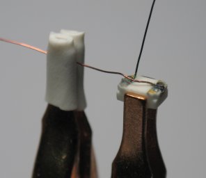
Holding of the 2x3 LEDs for soldering and holding the wires in accurate position is the essential part of the wiring process. After much experimenting, we have developed a tool (NT301) that does the job easily. It greatly simplifies the wiring process by holding both the LED and wire allowing you to have both hands free to make your solder connection. Shown below is a wired 2x3 LED with the anode (+) wire being held by the padded spring clip at the left. This tool works very well for all of our LEDs including our tiny Nanos.
-
Pick a pattern and stick with it. That is, get in the habit of soldering the cathode side first or the anode side first. We recommend using red wire for the anode (+) side. This follows normal electrical convention (the plus lead on your car battery or train power supply, for instance). The green wire for the cathode (-) side. If you're doing several, do all of one color first. We like to solder all of the cathode connections first because the LED face is marked with a small line denoting the cathode connection. Once this is done, there's no possibility for confusion (and shorting LEDs).
-
To solder the first wire, lay it down on the solder pad so that the point where the tinned portion of the wire stops and the insulation starts in lined-up with the back edge of the solder pad. Let the remainder of the tinned portion hang off the side of the solder pad. Or, you can pre-cut the wire so that the tinned portion is no wider than the solder pad. It's up to you. Follow the soldering procedure we covered in detail in the Using the wire section of the Magnet Wire, making sure to minimize the time your iron spends on the solder pad of the LED. If you've left the tinned part long, snip it flush with the edge of the LED. Carefully slicing it off with a sharp scalpel also works well. Don't nick the gold pad.
-
Gently bend the wire slightly to the side so it's not hanging over the other solder pad. How you position the second wire depends on how you're going to use the LED. If you're making an HO ditch light for example, you'll want both wires exiting the LED from the same side. In this case, you'll want to trim the second wire so that the tinned portion is only the width of the solder pad and position it so that insulation starts as the wire exits the pad. If this LED will be mounted as a floodlight, you'll probably want the wires to exit up away from the LED back and be twisted together. In this case, turn the LED around and solder the second wire so that it exits the LED in the opposite direction from the first wire.
-
If you've used additional flux, gently clean the back and sides of the LED.
-
A graphic representation of the above procedure in step-by-step format (wiring our Micro LEDs), including complete use of our NT301 LED/wire Holding Tool, will be very helpful and can be reviewed by clicking here..
Testing your work
Whether you're planning on wiring a bunch of LEDs or just one, we cannot overemphasize the importance of testing your work before placing wired LEDs in you structures or other projects.
Imagine building for example, a streetlight and discovering after the detailed assembly that somehow, the LED got fried or is shorted. At a minimum, strong words would likely ensue...
We use to recommend building a small portable tester and even included a circuit diagram and parts list on this page. Well, no more. We now carry an Intelligent LED Tester that is very inexpensive and will automatically test any 20ma LED regardless of color or pin configuration. It has a built-in state-of-the-art current source to ensure each LED receives 20ma (± 1%) current. Simply snap it onto a standard 9-volt battery and you're ready to go.
It's extremely portable so it can be used to see how different lights look at various places on a layout, or in and around different structures.
Happy testing and may all of your wired LEDs work the first time. Please let us know if you have any questions or problems.
© 2008 Ngineering