


Best viewed using:
Internet Explorer
or
Mozilla Firefox


Connecting the 1970's era police 4-LED lightbar and alternating headlights
Utilizing
the
one of the
industry’s
most advanced
microcontrollers
and
highly regulated
voltage control circuitry, this
total module consumes less than
40ma of current during normal operation with all LEDs attached. Input DC voltage
range is 5.6 to 20 volts.
Preparing the N8110-10:
The module’s
tiny size
and thin construction will allow it to be placed so it is easily hidden from
view. The module has circuitry
both sides so care must be taken when mounting to prevent
contact with metal (electrically conductive) material which could cause a
short circuit. The bottom of the circuit board can be used for mounting with the
small square double-sided sticky foam pad that is included.
Important
note:
A
low-wattage
iron (15-watt or less) should be used for this process and a needle type
pointed tip should be used for connection of the
wires
to the module. Too much heat or solder can
damage the wires,
LEDs
&
module and void warranty.
Figure 1
below shows a detailed view of the wires to be connected as viewed from the
front side of the circuit board.
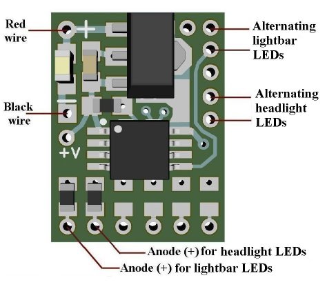
Figure 1
Soldering wires to the module:
The red and
black power wires should be stripped and tinned prior to attachment to the
circuit module. Strip approximately 1/4” of insulation from each end of each
wire and ensure the wire strands are twisted together and carefully tin each
end.
Each wire’s
tinned end should be inserted into the appropriate solder point
with the wire inserted from the front side of the board and soldered on
the back side of the board. For this process, good lighting, magnification, and
a method to hold the circuit while soldering will be very helpful in the
positioning of the wires.
Extra care must be taken when soldering wires in position.
Because of their close proximity, excess solder can easily cause bridging
between pads.
For best
success in soldering the wires,
place each wire into the appropriate solder hole and seat the insulation up
against the hole on the front side of the board. Ensure the wire is held in that
position when applying any flux and
solder to the hole on the back side of the board.
It is easiest if a small amount of solder is placed on the soldering iron
tip first, then the wire is placed in position and flux is applied
at the back side of the hole. While holding the wire in position, touch
the tinned wire strand and the hole with the soldering iron tip allowing the
solder to flow into the hole capturing the wire. This soldering process should
only take about 1/3 of a second to provide a clean shiny solder joint with no
excessive solder. Then, carefully snip the protruding wire from the solder
joint. This will ensure a good joint and eliminate possible shorting. Repeat
this process for all remaining wires.
Soldering
the LED wires to the module requires the same care as outlined above. If the LED
wires are single-strand magnet wires, ensure they are properly stripped
and pre-tinned
prior to soldering them in place.
Testing and mounting the assembly:
The N8110-10
Simulator assembly is now completed and should be tested prior to installation.
Figure 2 below shows a schematic view of LED connections.
NOTE: This
module DOES NOT HAVE
reverse polarity power protection, so be extra careful when connecting the
+DC RED
wire and the –DC BLACK
wire to your power source. Connecting the backwards
will damage the module.
Once power
has been applied and all LEDs appear to be function normally, the assembly can
be mounted into your project.
Included in this package is a small double-sided sticky foam pad for this
purpose.
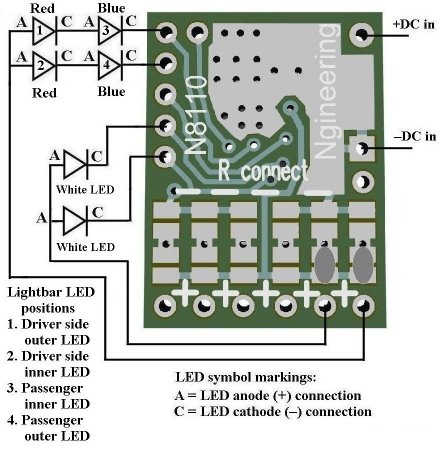
Figure 2
This completes connection of the N8110-10 module. We hope you enjoy the added realism our module provides.
© 2021 Ngineering