


Best viewed using:
Internet Explorer
or
Mozilla Firefox


Connecting the N8064B-2 Gas Welder Simulator & N8X0X-092 Gas Welder Sound
Product &
installation overview:
The N8064B-2
simulates the startup and operation of an Oxy/Acetylene (gas) welding or cutting
torch by intermittently varying the intensity and duration of two LEDs (one
white & one yellow).
The
–2
version is programmed with correct timing to function with our N8301-092 or
N8501-092 Sound modules. See page 3 for wiring diagram.
Utilizing
the industry’s smallest
microcontroller and associated voltage control circuitry, the total module
consumes less than 1/2 ma. Typical peak operating current with the LED attached
and running is about 18 ma. This makes
it
ideally suited for operation with batteries, or any well-filtered and regulated
DC power source with an output of 6-18VDC.
Connecting the N8064B-2:
Installing
the N8064B-2
is very straightforward. Its tiny size and thin construction will allow it to be
adapted to nearly any modeling scale.
Because the module has circuitry on both sides, care must be taken to be
sure that the components or wires soldered will not make contact with any metal
object which could cause a short
circuit.
Included
with the module are three
6” lengths of #32 insulated wire. If desired, these can be used for power input
& control
wires. In this case, the red wire can be connected to solder point
1
(the +DC connection) and the black wire can be connected to solder point
2 (DC-).
The violet wire can be connected to point
6
for input control.
See Fig. 1 below.
Important
note:
A
low-wattage iron with a pointed tip should be used for connection of wires. Too
much heat or solder can easily damage the wires, decoder or module and void the
warranty.
Also, all
connecting wires should be pre-tinned before soldering them to the module. This
will make connection quick and easy and ensure excessive heat is not applied to
the solder points.
When
connecting the LEDs, proper polarity must be observed. LEDs are “polarity
sensitive” and will not function if connected backwards
Figure 1
The N8064B-2
is configured for connection of two 20 ma LEDs. A white LED with a device
voltage of 2.8-3.6 VDC (Ngineering’s 2x3 LEDs, Micro & Nano white LEDs, as well
as many white LEDs available), and a yellow LED with a device voltage of 2.0 VDC
(Ngineering’s Micro & Nano yellow LEDs, as well as many other yellow LEDs ).
Using wire
appropriate for the size of the LED and its placement in the project, connect
the white LED
anode (the
+ connection) to solder point
4. Connect the
cathode
(- connection) of this LED to solder point
3.
Connect the yellow LED’s
cathode
is to solder point
5,
and its anode
also to solder point 4.
If more convenient, the two LEDs anodes can be wired together and a single wire
can be connected to solder point 4.
Whatever makes it easiest is
the best approach. Both LED will use the N8064B module’s on-board current
limiting resistor, so no external resistor is required.
Figure 2
(below) is a schematic diagram of the connections required.
Figure 2
Positioning and soldering the LEDs:
When soldering the 2 LEDs, how the welder will be
viewed is key to how the LEDs will be located with respect to each other. If the
arc welder is to be viewed indirectly, that is, if the LEDs are to be hidden
from direct view but seen as flashes and floods of light being cast about of
other objects, then they should be relatively close to each other so the effects
appear to come from a common source.
This can easily be achieved by just
placing them near each other after they have been wired. An example of this is
our video of the welding being performed under the Mustang drag racer at Tiny’s
Welding on our website.
On the other hand, if the effect is to be viewed directly like the welder
working on the truck at Tiny's, then it is very important that the LEDs be
physically located as close to each other as possible (without the cathode ends
of the LEDs shorting to each other). This is so that when the Simulator is
energizing the LEDs, their close proximity gives the best possible appearance of
one light source. Below
in Figure 5 we show an example of 2 Nano LEDs aligned side by side. Notice the
placement of a very thin shim at the cathode ends between the LEDs. There are
many different materials that can be used for the shim, but the material chosen
must meet certain criteria.
If the shim is to be temporary (only in position during soldering), it can be
any material that solder will not stick to during the soldering operation. A
good choice here would be regular aluminum foil. It meets the thickness
requirements at about .002" and solder will not stick to it.
If the shim is to be left in place between the LEDs permanently, then it must be
made of non-conductive material such as .001" or >002" Kapton tape. This
material is an excellent choice because it is high-temperature material that can
withstand the soldering operation and it has good insulating properties.
Shim positioning should be such that it ensures total blockage of adjacent
cathode conductors. Notice that the solder pads on these LEDs actually wrap
around from the back (solder pad side) of the tiny circuit board to the front
and go under the epoxy capsule where the LED light is emitted. This is how they
make connection with the LED chip inside the capsule. When viewed on edge, this
conductive circuit that wraps around extends completely to the edge (side) of
the LED (see Fig. 3). If two Nano LEDs were pushed against each other, these
conductors would short against each other. For this reason, we need to shim.
Figure 3
The 2 LEDs
can be positioned face down and aligned against brass, steel, or styrene strips
double side taped to a flat surface. These strips or rails will help to hold the
LEDs in position. The strips should be thin enough to let the LED faces contact
the double-sided tape and assist in holding them in place. The shim to be placed
between the cathode conductors only need to be "tall" enough completely block
cathode contact. It doesn't need to protrude up any higher than is necessary to
be grasped with tweezers for its removal after the soldering operation. If it is
to be left in place (Kapton tape for example) it should be not so "tall" as to
block the light emitting between the adjacent LEDs.
Once the
soldering is done and the 2 anodes are bridged and wires are connected the 2
LEDs will remain positioned as soldered so that the cathodes do not touch, even
if the shim is removed. The anode bridge is sufficient to maintain alignment
(see Fig. 4). However, the LED assembly should be treated delicately. Undue side
pressure can crack the solder bridge and change alignment.
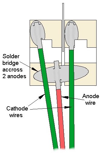
Figure 4
This
completes
connection
of the N8064B
gas welder simulator.
The N8064B-2 is
programmed to start the lighting effect when the input control pin (6) is
connected to ground (-DC). This coincides with the starting of the sound effect
that is outputted from the –092 sound module. The example below (Figure 5) is
shown of a N8501-092 Little Bigger Sounds module and amplifier.
If the sound
module being used is a N8301-092 (Little Sounds without the external amplifier)
the connections wound be the same between the sound board and the welding
Simulator.
A push button
switch is shown for the start control since only momentary grounding (-DC) is
required to start both effects which will run through to the end of the effect
and stop.
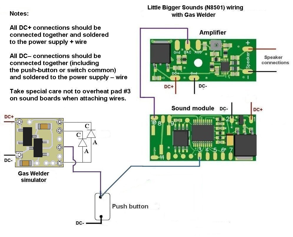
Figure 5
This
completes the LED and Sound circuit wiring for the N8064B-2.
© 2022 Ngineering