


Best viewed using:
Internet Explorer
or
Mozilla Firefox


Connecting the N8094 Enterprise NCC1701 Phaser & N8095 Enterprise NCC1701A Phaser Simulators
The N8094
is designed to simulate the
approx. 4-second burst of red light as seen when firing a
phaser cannon
on-board the early NCC-1701 Star trek Enterprise. and
the N8095
is designed to simulate the
approx. 4-second burst of blue light as seen when firing a
phaser cannon
on-board the early NCC-1701A
Note: Different circuits are required for the two versions of phaser simulators because red and blue LEDs have dirrferent device voltages and require different current limiting resistors to be mounted on the simulators.
Installing the N8094 or N8095 simulators are very straightforward. Their tiny size and thin construction will allow them to be placed nearly anywhere in any scale model. Because the modules have circuitry on both sides, care must be taken to be sure that the components or wires soldered will not make contact with any metal object causing a short circuit.
These simulators can be powered by battery or any well-filtered and regulated DC power source with an output of 6-18VDC.
Included with the module are three 6” lengths of #32 insulated wire. These can be used for power & input control wires. In this case, the red wire can be connected to solder point 1 (the +DC connection), the black wire to solder point 2 (DC-), and the violet wire to point 5. See Fig. 1 below for connection points
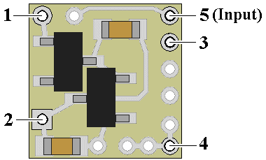
Figure 1
Important note: A low-wattage iron with a pointed tip should be used for connection of wires. Too much heat or solder can easily damage the wires, decoder or module and void the warranty.
Also, all connecting wires should be pre-tinned before soldering them to the module. This will make connection quick and easy and ensure excessive heat is not applied to the solder points.
Connecting LEDs
When connecting LEDs, proper polarity must be observed. LEDs are “polarity sensitive” and will not function if connected backwards. The N8094 is configured to connect a single 20 ma red LED with a device voltage of 1.75-2.0 VDC between solder points 3 & 4. (this covers all of Ngineering’s red LEDs, as well as most red LEDs available). This LED will use the N8094’s on-board current protection resistor.The N8095 is configured to connect a single 20ma blue LED with a device voltage of 2.8-3.0 VDC between solder points 3 & 4. (this covers all of Ngineering’s blue LEDs, as well as most blue LEDs available). This LED will use the N8095’s on-board current protection resistor.
Use wire
appropriate for the size of the LED and its placement in the model.
Connect
the
LED anode
to solder point
4.
Connect the LED
cathode
to point
3.
Figure 2
(below) is a schematic diagram of the connections required.
.
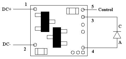
Figure 2
Once again, be sure to use a low-wattage soldering iron when connecting wires to the module. Our N40M2 12-watt Iron with either the N408I (iron clad) Needle Tip, or the N408X (bare copper) Needle Tip would be an excellent choice for this operation.
Input control
Solder point 5 can be connected to any switch (momentary pushbutton or magnetic reed switch) which is tied to -DC (ground).
This completes hookup of our N8094/95 phaser simulators. We hope the added realism it provides enhances your enjoyment of the hobby.
© 2025 Ngineering