


Best viewed using:
Internet Explorer
or
Mozilla Firefox


Connecting the NB8041 6-LED Modern Alternating Flasher Simulator
Installing the NB8041 is very straightforward. Because the module has circuitry on both sides, care must be taken to be sure that the components or wires soldered will not make contact with any metal object which could cause a short circuit.
Included with the module are three 6” lengths of #32 insulated wire. If necessary, these can be used for power input wires. If used, we recommend the red wire be used for the + DC connection. It would be connected to solder point 1 as shown in Fig. 1. This wire could also connect through a switch to the + DC connection for remote control of the lighting effect. The black wire should be connected to – DC and to solder point 2. The violet ire should be connected to point 14 for control of the effect.
Any well regulated DC power source can be used to power this module providing the voltage is at least 6VDC and doesn't exceed 18VDC. Our N3512B or N3518 Power supplies are ideal for this use. Also, due to the very low power consumption, this device can also be powered by a battery, such as a standard 9-volt.
Important note: A low-wattage iron with a pointed tip should be used for connection of wires. Too much heat or solder can easily damage the wires or module and void the warranty.
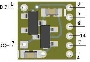
Figure 1
Connecting LEDs
When
connecting the LEDs, proper polarity must be observed. LEDs are “polarity
sensitive” and will not function if connected backwards.
The NB8041
is configured for connection of three
series pairs of 20 ma LEDs. Each pair consists of two
red LEDs
(typical device voltage of 1.75-2.0
VDC). One pair is wired to solder points
3
&
4..
The second pair is connected to solder points
5
&
4
The third pair is to be connected to points
6
&
7.
The NB8041
has
two on-board current limiting resistors
which protects
all series LED pairs
connected
Using wire
appropriate for the size of the LEDs and their placement in the model, connect
the wire from
the
red
LED
cathode (the – connection) to point
3
on the module and the wire from its anode
(the +) to the wire connected to the cathode
of the (red) LED (the 2nd LED of the series pair). Connect the wire from the
anode of this 2nd LED to solder point
4.
Connect the wire from the red
LED
cathode to point 5
on the module and the wire from its anode
to the wire connected to the cathode
of the (red) LED (the 2nd LED of the 2nd series pair). Connect the wire from the
anode of this LED to solder point
4.
Repeat the above procedure for the third series pair and ire them between solder
point 6
and
7
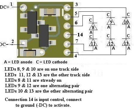
Figure 2
Once again, be sure to use a low-wattage soldering iron when connecting wires to the module.
This completes hookup of our NB8041 Modern Alternating Flasher module. We hope the added realism it provides enhances your enjoyment of the hobby.
© 2025 Ngineering