


Best viewed using:
Internet Explorer
or
Mozilla Firefox


Connecting the NLA8031B &NLD8031B Super-Marslight Simulator
Installing the NLA8031B or NLD8031B is very straightforward. Its tiny size and thin construction will allow it to be placed in many spaces too small for even the smallest Z-scale decoder. Because the module has circuitry on both sides, care must be taken to be sure that the components or wires soldered will not make contact with any metal object (such as a locomotive frame) causing a short circuit.
Included with the module are two 6” lengths of #32 insulated wire. If necessary, these can be used for power input wires.
NLA8031B (analog) input power connections:
The NLA8031/A Simulator is configured for analog (DC) operating environments. It will function normally with track voltages ranging from 3.2 to 16-volts DC. The circuit includes a Schottky barrier diode to protect the module from reverse input voltage polarity. This means when it is wired the normal "engineer's side is the +DC track side", the effect is fully operational. when running in reverse "fireman's side is the +DC track side) the effect is not in operation. For many lighting effects, this will not be a problem because they are intended for forward operation.
For those effects that need full bi-directional operation, one of our N8101 DC Power Source circuits can be added in front of the effect simulator board to eliminate DC polarity issues. The N8101 contains a very-low voltage-drop Schottky bridge rectifier which will slightly raise the startup voltage threshold of the lighting effect by about 0.2-0.4 volts. Figure 2 below below is schematic diagram of the connections required.
All solder connections explained below
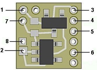
Figure 1
NLD8031B (DCC/RC) input power connections:
The NLD8031/B Simulator is configured for DCC environments and sound decoders having 3.3-volt accessory functions It has an on-board jumper in place of the barrier diode used in the analog version. This allows them to operate fully at 3.3-volts (even slightly, below allowing for LED brightness). Since track polarity is not a factor in DCC the need for this protection is not required. Also, in an RC modeling environment, battery power is known so this is not an issue. However, since this family of Simulators doesn't have polarity protection, care must be taken during wiring to ensure polarity is correct before power is applied. Otherwise, the circuitry will be damaged. Figure 3 below shows the front side of the NLD8031/B with the jumper installed and the barrier diode not installed.
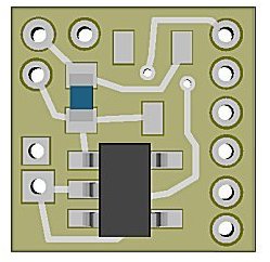
Figure 3
In a DCC environment, most wired decoders have a blue wire which is the common connection for all wired functions (F0, F1, etc.). It is the + DC connection and will be connected to solder point #1 as shown in Fig. 1.
If the decoder is a “drop-in” style without wires, consult the decoder manual and use the blue wire supplied to connect point #1 to the appropriate + solder pad.
If the solder pad has a resistor in series with it, be sure to connect the blue wire behind the resistor (see Fig. 4). This will ensure full voltage is supplied to the module.
Figure 4
Important note: A low-wattage iron with a pointed tip should be used for connection of wires. Too much heat or solder can easily damage the wires, decoder or module and void the warranty.
Also, all connecting wires should be pre-tinned before soldering them to the module. This will make connection quick and easy and ensure excessive heat is not applied to the solder points.
Next, choose the function you want to control the NLD8031B module and connect the appropriate function wire to solder point #2. For example: If you want F1 to turn on the Super-Marslight, connect the green wire to #2.
Again, if the decoder is the drop-in style, use the enclosed green wire to connect the appropriate function solder pad to #2. Make sure the pad chosen for this connection is not a “+” pad , but a function pad (– DC connection).
Whichever function you choose, make sure it is programmed for On/Off control only. Do not program the function for special effects. The NLD8031B will control the special effects.
Connecting LEDs
When connecting LEDs, proper polarity must be observed. LEDs are “polarity sensitive” and will not function is connected backwards. The NLA8031B and NLD8031B are configured to connect three (3) 20 ma LEDs with a device voltages of 3.2-3.3 VDC. This covers all of Ngineering’s white, yellow-white and incandescent white LEDs, as well as most of the white and golden-white LEDs available. These LEDs will use the Simulator's on-board resistor for current protection and, will be connected in what is referred to as "common-anode" wiring. See Fig. 5 below.
Figure 5
Soldering the LEDs
When soldering the 3 LEDs to be used with the Super-Marslight, it is very important that they be physically located as close to each other as possible (without the cathode ends of the LEDs shorting to each other). The reason for this is so that when the Simulator is energizing the LEDs sequentially, their close proximity gives the appearance of one light source sweeping back and forth (the Marslight effect). Below in Figure 6 we show an example of 3 Nano LEDs aligned side by side. Notice the placement of a very thin shim at the cathode ends between the LEDs. There are many different materials that can be used for the shims, but the material chosen must meet certain criteria.
If the shims are to be temporary (only in position during soldering), they can be any material that solder will not stick to during the soldering operation. A good choice here would be regular aluminum foil. It meets the thickness requirements at about .002" and solder will not stick to it.
If the shims are to be left in place between the LEDs permanently, then they must be made of non-conductive material such as .001" or >002" Kapton tape. This material is an excellent choice because it is high-temperature material that can withstand the soldering operation and it has good insulating properties.
With regard to positioning of the shims, they should be positioned to ensure total blockage of adjacent cathode conductors. Notice that the solder pads on these LEDs actually wrap around from the back (solder pad side) of the tiny circuit board to the front and go under the epoxy capsule where the LED light is emitted. This is how they make connection with the LED chip inside the capsule. When viewed on edge, this conductive circuit that wraps around extends completely to the edge (side) of the LED. If two Nano LEDs were pushed against each other, these conductors would short against each other. For this reason, we need to shim.
Figure 6
The 3 LEDs can be positioned face down and aligned against brass, steel, or styrene strips double-side taped to a flat surface. These strips or rails will help to hold the LEDs in position along their bottom and side edges. The strips should be thin enough to let the LED faces contact the double-sided tape and assist in holding them in place. The shims to be placed between the cathode conductors only need to be "tall" enough completely block cathode contact. They don't need to protrude up any higher than is necessary to be grasped with tweezers for their removal after the soldering operation. If they are to be left in place (Kapton tape for example) they should be not so "tall" as to block the light emitting between two adjacent LEDs.
It is worth noting that once the soldering is done and the 3 anodes are bridged, and wires are connected, the 3 LEDs will remain positioned as soldered so that the cathodes do not touch, even if the shims are removed. The anode bridge is sufficient to maintain alignment. However, the LED assembly should be treated delicately. Undue side pressure can crack the solder bridge and change alignment. Figure 7 below shows the LEDs soldered with wires attached. Our recommendation is that the wires be carefully routed up and away from the rear of the LED assembly, similar to "back wiring" as shown in Advanced Lighting, Figure 2, here.
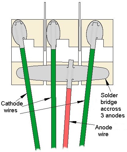
Figure 7
When connecting the wires to the NLA8031B or NLD8031B Simulators it is very important that the correct cathode wire is connected to the correct solder point on the board. The center LED cathode wire must be connected to solder point 4 for the proper lighting effect to occur. The remaining 2 cathode wires can be connected to either solder point 3 and 5 or reversed (5 and 3). Those two connections only determine which direction the Mars action starts from (left side first, or right side first). The anode wire is of course connected to solder point 6 as shown in figure 5 above.
Flicker control
Another new feature we've added to our low-voltage Simulator modules is solder-points for direct wiring of external capacitors for flicker control. These are solder points 7 and 8. When connecting external capacitance for this purpose, if multiple capacitors are used, they must be wired in parallel (all + connections together, and all – connections together). They must have a voltage rating of 16-volts or greater. The + (plus) connections are to be wired to solder point 7 and the – (minus) connections wired to point 8. For this Super Marslight Simulator, a capacitance value of 100 to 300uf will be sufficient.
Once again, be sure to use a low-wattage soldering iron when connecting wires to the module. Our N40M2 12-watt Iron with either the N408I (iron clad) Needle Tip, or the N408X (bare copper) Needle Tip would be an excellent choice for this operation (or any DCC decoder work).
This completes hookup of our NLA8031B & NLD8031B Super Marslight Simulator modules. We hope the added realism it provides enhances your enjoyment of the hobby.
© 2009 Ngineering