


Best viewed using:
Internet Explorer
or
Mozilla Firefox


Connecting the N8031B Super-Marslight Simulator
Installing the N8031b is very straightforward. Its tiny size and thin construction will allow it to be placed in many spaces too small for even the smallest Z-scale decoder. Because the module has circuitry on both sides, care must be taken to be sure that the components or wires soldered will not make contact with any metal object (such as a locomotive frame) causing a short circuit.
If the N8031B is to be used in a stationary (not track powered) application, it can also be powered by any well-filtered and regulated DC power source with an output of 6-18VDC.
Included with the module are two 6” lengths of #32 insulated wire. If necessary, these can be used for power input wires.
Most wired decoders have a blue wire which is the common connection for all wired functions (F0, F1, etc.). It is the + DC connection and will be connected to solder point #1 as shown in Fig. 1.
If the decoder is a “drop-in” style without wires, consult the decoder manual and use the blue wire supplied to connect point #1 to the appropriate + solder pad.
Figure 1
If the solder pad has a resistor in series with it, be sure to connect the blue wire behind the resistor (see Fig. 2). This will ensure full voltage is supplied to the module.
Important note: A low-wattage iron with a pointed tip should be used for connection of wires. Too much heat or solder can easily damage the wires, decoder or module and void the warranty.
Also, all connecting wires should be pre-tinned before soldering them to the module. This will make connection quick and easy and ensure excessive heat is not applied to the solder points.
Next, choose the function you want to control the N8031B module and connect the appropriate function wire to solder point #2. For example: If you want F1 to turn on the Super-Marslight, connect the green wire to #2.
Again, if the decoder is the drop-in style, use the enclosed green wire to connect the appropriate function solder pad to #2. Make sure the pad chosen for this connection is not a “+” pad , but a function pad (– DC connection).
Whichever function you choose, make sure it is programmed for On/Off control only. Do not program the function for special effects. The N8031 will control the special effects.
Direct Track powering (without a decoder connection)
All of our Simulators require a clean DC voltage of known polarity for their power source to function properly. If wired up with DC polarity reversed, the Simulator has on-board protection to prevent damage, but it will not operate until correct power input polarity is established. Track power is typically provided in one of two forms. DC voltage (analog), or DCC.
Analog track power has been around for more than 75 years. Simply put, a DC voltage is applied to the two tracks with one being +DC and the other, -DC. Increase the voltage and the electric motor in the locomotive spins faster making the train go faster. If the train is required to reverse, track polarity is reversed so the loco's motor turns in reverse. Also, what defines "forward and reverse" is dependent on which way the loco is facing when it's put on the track. Bottom line here is that track polarity is not fixed. Our Simulator needs fixed polarity for continuous operation.
DCC track power is such that to devices requiring plain DC voltage, it looks like AC power. That is because voltage levels on each track go both + and – continuously. The DCC decoders in locomotives “descramble” the track signals and provide correct polarity so their motors can function normally. It is this process that will allow multiple locomotives to go in different directions on the same section of track, at the same time (a feature not available with analog track power). Once again, our Simulator needs fixed polarity and it needs to look like DC voltage.
Due to our Simulator's very small size, there is insufficient space to include additional circuitry and components necessary for proper power conditioning when direct track pickup is to be used. There are two solutions to this problem and both are inexpensive:
Discrete components
The Simulator can be powered from the track with the addition of two readily available components: a bridge rectifier (our N301S or N302S will work just fine). If DCC operation is used, the addition of a filter capacitor (10μf or larger and minimum 16-volt) will be required. Figure 3 below is schematic diagram of the connections required.
Figure 3
This is the least expensive solution, but is has a couple of minor drawbacks. First, the bridge rectifier (and capacitor, if needed) are not mounted on a circuit board so direct solder connection is required and you will need to ensure the pins on the rectifier and leads on the capacitor (depending on the type of capacitor) are organized so that they won't short out against anything. Second, depending on the physical size of the bridge selected (and capacitor, if needed) and the scale you're modeling, hiding these additional components so they're not noticeable can be a bit of a challenge.
N8101 DC Power Source
A more elegant, but very slightly more costly ($3.95) solution would be to use our N8101 DC Power Source. It has all of the components needed, includes a circuit board with solder points, is extremely tiny (1/2 the size of our Simulator), has the lowest possible voltage loss (important for analog operators). Click here for more information on the N8101. Figure 4 below is schematic diagram of the connections required.
Figure 4
Connecting LEDs
When connecting LEDs, proper polarity must be observed. LEDs are “polarity sensitive” and will not function is connected backwards. The N8031B is configured to connect three (3) 20 ma LEDs with a device voltages of 3.3-3.6 VDC. This covers all of Ngineering’s white, yellow-white and incandescent white LEDs, as well as most of the white and golden-white LEDs available. These LEDs will use the Simulator's on-board resistor for current protection and, will be connected in what is referred to as "common-anode" wiring. See Fig. 5 below.
Figure 5
Soldering the LEDs
When soldering the 3 LEDs to be used with the Super-Marslight, it is very important that they be physically located as close to each other as possible (without the cathode ends of the LEDs shorting to each other). The reason for this is so that when the Simulator is energizing the LEDs sequentially, their close proximity gives the appearance of one light source sweeping back and forth (the Marslight effect). Below in Figure 6 we show an example of 3 Nano LEDs aligned side by side. Notice the placement of a very thin shim at the cathode ends between the LEDs. There are many different materials that can be used for the shims, but the material chosen must meet certain criteria.
If the shims are to be temporary (only in position during soldering), they can be any material that solder will not stick to during the soldering operation. A good choice here would be regular aluminum foil. It meets the thickness requirements at about .002" and solder will not stick to it.
If the shims are to be left in place between the LEDs permanently, then they must be made of non-conductive material such as .001" or >002" Kapton tape. This material is an excellent choice because it is high-temperature material that can withstand the soldering operation and it has good insulating properties.
With regard to positioning of the shims, they should be positioned to ensure total blockage of adjacent cathode conductors. Notice that the solder pads on these LEDs actually wrap around from the back (solder pad side) of the tiny circuit board to the front and go under the epoxy capsule where the LED light is emitted. This is how they make connection with the LED chip inside the capsule. When viewed on edge, this conductive circuit that wraps around extends completely to the edge (side) of the LED. If two Nano LEDs were pushed against each other, these conductors would short against each other. For this reason, we need to shim.
Figure 6
The 3 LEDs can be positioned face down and aligned against brass, steel, or styrene strips double-side taped to a flat surface. These strips or rails will help to hold the LEDs in position along their bottom and side edges. The strips should be thin enough to let the LED faces contact the double-sided tape and assist in holding them in place. The shims to be placed between the cathode conductors only need to be "tall" enough completely block cathode contact. They don't need to protrude up any higher than is necessary to be grasped with tweezers for their removal after the soldering operation. If they are to be left in place (Kapton tape for example) they should be not so "tall" as to block the light emitting between two adjacent LEDs.
It is worth noting that once the soldering is done and the 3 anodes are bridged, and wires are connected, the 3 LEDs will remain positioned as soldered so that the cathodes do not touch, even if the shims are removed. The anode bridge is sufficient to maintain alignment. However, the LED assembly should be treated delicately. Undue side pressure can crack the solder bridge and change alignment. Figure 7 below shows the LEDs soldered with wires attached. Our recommendation is that the wires be carefully routed up and away from the rear of the LED assembly, similar to "back wiring" as shown in Advanced Lighting, Figure 2, here.
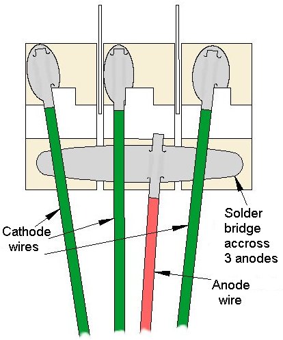
Figure 7
When connecting the wires to the N8031B Simulator it is very important that the correct cathode wire is connected to the correct solder point on the board. The center LED cathode wire must be connected to solder point 4 for the proper lighting effect to occur. The remaining 2 cathode wires can be connected to either solder point 3 and 5 or reversed (5 and 3). Those two connections only determine which direction the Mars action starts from (left side first, or right side first). The anode wire is of course connected to solder point 6 as shown in figure 5 above.
Analog (DC) operational note for the N8031B:
In some DC operational circumstances, the need to control headlight flicker as a result of track gaps or dirt may not be of concern or deemed important enough to worry about.
If this is the case and track voltage will never exceed 18-volts, the N8031B can be wired directly to the track pickups (solder point 1 to Engineer's side, solder point 2 to Fireman's side), and will function properly for locomotive direction control. That is, when the loco is in reverse the Marslight (and headlight if using the N8031A) will be turned off because the module's on-board polarity protection will shut down the Simulator. When forward motion is reestablished the module will turn back on.
This completes connection of the N8031B module. It is recommended that a thorough re-inspection of all connections and module placement be performed prior to applying power to the locomotive. We hope you enjoy the added realism our module provides.
© 2009 Ngineering