Best viewed using:
Internet Explorer
or
Mozilla Firefox
Connecting the N8101 & N8101B DC Power Source
Connecting and using the N8101 or the N8101B is very straightforward. Its tiny size and thin construction will allow it to be placed nearly anywhere, even if you're modeling Z-scale.
Included with the module are two 6” lengths of #32 insulated wire. If needed, these can be used for power input or output wires.
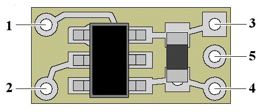
Solder points #1 and #2 are the power input connections. Power input to the N8101 can be up to 16-volts, and can be either AC voltage (not exceeding 11.3-volts RMS), DC voltage of changeable polarity, or DCC track power. Solder point #3 is -DC output (or ground), and solder point #4 is +DC output. See figure 1 below. The N8101B power input can be up to 25 volts DC or AC of 17.8-volts RMS.
Note: Solder point #3 is square in shape to aid in easy visual differentiation.

Figure 1
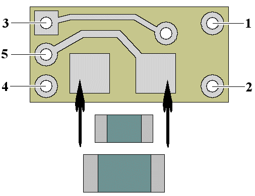
Also included on the N8101 is solder point #5. This is an optional connection point provided for +DC resisted voltage output to a polarity sensitive device such as an LED. Figure 2 below shows the back side of the N8101. Shown are the two solder pads provided for either an 1/8-watt or 1/4-watt surface-mount type resistor. When a resistor is installed, the circuit through to solder point #5 is completed so the resistor is in series with the +DC output #5. Connecting a device such as an LED between #5 and #3 will provide power for the LED.
Note: For proper LED operation, resistor selection must be calculated based on maximum expected input voltage. If assistance is needed to determine the proper resistor, click here for an in-depth explanation.
When connecting an LED to the module, proper polarity must be observed. LEDs are “polarity sensitive” and will not function if connected backwards. Using wire appropriate for the size of the LED and its placement, connect the LED cathode (the – connection) to point #3 on the module and connect the LED anode (the +) to solder point #5.

Figure 2
Important note: A low-wattage iron with a pointed tip should be used for connection of wires. Too much heat or solder can easily damage the wires, or the module and void its warranty. When soldering a resistor to the pads shown in figure 2 above, pay particular attention to the left pad (closest to solder points 3, 4 & 5). This solder pad also connects to the filter capacitor on the front-side of the board. Excessive heat during resistor soldering on this pad could conduct through the board and cause the capacitor to partially desolder from the circuit.
Also, all connecting wires should be pre-tinned before soldering them to the N8101. This will make connection quick and easy and ensure excessive heat is not applied to any solder points.
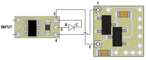
Shown in Figure 3 below, is an example of the N8101 wired to a N80XX type Simulator and using the optional LED connection (solder point 5). Note the LED's anode connection to 5 and its cathode connection to 3 on the N8101. This LED could actually be a series group if the input voltage is sufficient to support multiple LEDs). Again, the resistor soldered to the solder pads on the back of the N8101 should be chosen for protection of the LED (or series group) at maximum expected input voltage.

Figure 3
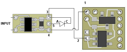
Shown in Figure 4 below is the same connection example, but with a NLA/D80XX Low-voltage Simulator

Figure 3
In the examples above, we could add additional Simulators by connecting their inputs to solder points 3 and 4 of the N8101, just as the one above. Or, we could add additional LEDs (or series groups) by connected them to solder points 3 and 4 (not to 3 and 5). These additional LEDs will need their own resistors wired in series with them.
The limiting factor for the number of devices (Simulators and/or LEDs) connected to an N8101's output pins 3 and 4 is that the total power usage (power = voltage x current) for all devices added together must not exceed 350mW (0.350 Watts).
This completes connection of the N8101 & N8101B DC Power Source. It is recommended that a thorough re-inspection of all connections and module placement be performed prior to applying power.
© 2021 Ngineering


