


Best viewed using:
Internet Explorer
or
Mozilla Firefox


Connecting the N8073 Turn signal & Hazard Light Simulator
Installing the N8073 is very straightforward. Its tiny size and thin construction will allow it to be placed in many locations, even in the smallest scale structures. Because the module has circuitry on both sides, care must be taken to be sure that the components or wires soldered will not make contact with any metal object and cause a short circuit.
Included with the module are four 6” lengths of #32 insulated wire. If necessary, these can be used for power input wires. If used, we recommend the red wire be used for the + DC connection. It would be connected to solder point 1 as shown in Fig. 1. This wire could also connect through a switch to the + DC connection for remote control of the lighting effect. The other (black) wire should be connected to – DC and to solder point 2. The violet & blue wires can be used for input control wiring.
Any well regulated DC power source can be used to power this module providing the voltage is at least 6VDC and doesn't exceed 18VDC. Our N3512 and N3518 Power supplies are ideal for this use. Also, due to the very low power consumption, this device can also be powered by a battery, such as a standard 9-volt.
Important note: A low-wattage iron with a pointed tip should be used for connection of wires. Too much heat or solder can easily damage the wires or module and void the warranty.
Also, all connecting wires should be pre-tinned before soldering them to the module. This will make connection quick and easy and ensure excessive heat is not applied to the solder points.
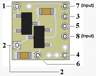
Figure 1
Connecting LEDs
When connecting the LEDs, proper polarity must be observed. LEDs are “polarity sensitive” and will not function if connected backwards. The N8073 is configured for connection of two series pairs of 20 ma LEDs. Each pair consists of one yellow (amber) LED (typical device voltage of 2.0 VDC), & one red LED (typical device voltage of 1.75-2.0 VDC). One pair is wired to solder points 4 & 5 (left-side turn signals). The second pair is connected to solder points 3 & 6 (right-hand turn signals).
The N8073 has one on-board current limiting resistor which protects the left-side series LED pair connected to solder points 4 & 5.. Also, included with this module, is a 1/8-watt 81-ohm SMD resistor (plus a spare) to be used for current protection of the right-side series LED pair that will be connected between points 3 & 6.
Using wire appropriate for the size of the LEDs and their placement in the model, connect the wire from right-front (amber) LED cathode (the – connection) to point 3 on the module and the wire from its anode (the +) to the wire connected to the cathode of the right-rear (red) LED (the 2nd LED of the series pair). Connect the wire from the anode of this 2nd LED to solder point 6. Connect the wire from the left-front (amber) LED cathode to point 5 on the module and the wire from its anode to the wire connected to the cathode of the left-rear (red) LED (the 2nd LED of the 2nd series pair). Connect the wire from the anode of this LED to solder point 4. See Fig. 2 below for a schematic layout of LED hookup.
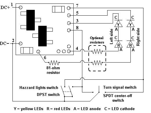
Figure 2
Simulator operation:
1. Right Turn Signal operation:
Solder point 7 is input control for the right turn signal function. Connecting this point to DC – (point 2) turns on the right turn signal. It will continue to blink as long as this point is connected to point 2
2. Left Turn Signal operation:
Solder point 8 is input control for the right turn signal function. Connecting this point to DC – (point 2) turns on the right turn signal. It will continue to blink as long as this point is connected to point 2
3. Hazard Light operation:
Hazard flasher are enabled by simultaneously connecting points 7 and 8 to DC – (point 2). Hazards will continue to flash as long as these two points are connected to point 2.
Choosing switches to control operations:
Turn Signals:
Shown in figure 2 below are electrical symbols for two types of switches that should be used for easy control of the turn signal and hazard functions. Vehicle turn signals are typically controlled by a 3-position switch. This switch is a SPDT center-off type (Single-Pole, Double-Throw). The wiper (or common terminal) is connected to DC –. Each one of the other terminals is connected to points 7 and 8. Switching from center-off to either position will activate that input function. If a SPDT type toggle switch is not available, a DTDP (Double-Pole, Double-Throw) type can be substituted, just make sure it has the center-off position. In this case, you would only be using one-half of the switch.
Hazard Flashers:
The hazard flasher is activated by connecting both points 7 & 8 to DC– (point 2)at the same time. The easiest way to do this is using a DPDT switch that does not have a center-off position. One side of the double-pole switch is left un-connected and the two wiper pins (commons) are wired together and connected to DC–. Points 7 and 8 are each connected to one of the other two poles (pins) This way, when the switch is thrown, the common wipers connect points 7 & 8 to DC– at the same time. This is essentially the way automotive manufactures control these operations, except those hazard switches are usually DPDT push-button types.
LED brightness:
Included with this module are two 150-ohm resistors (marked 1500) plus a spare, and two 510-ohm resistors (marked 5100) plus a spare. As shown in figure 2 below, these can be added in series with the wires from the RED LED anodes to increase the amount of resistance and lower brightness of the connected LED pairs. We’ve included the two different values so you have a choice of the amount of dimming (if any) is needed. In any case, make sure the right side red LED anode is wired with the included 81-ohm resistor to point 6. Failure to include this resistor will permanently damage the right side LEDs.
Once again, be sure to use a low-wattage soldering iron when connecting wires to the module. Our N40M2 12-watt Iron with either the N408I (iron clad) Needle Tip, or the N408X (bare copper) Needle Tip would be an excellent choice for this operation.
This completes connection of our N8073 module. We hope the added realism it provides enhances your enjoyment of your modeling project.
© 2012 Ngineering