Best viewed using:
Internet Explorer
or
Mozilla Firefox
N8102 LED Power Distribution Board Layout
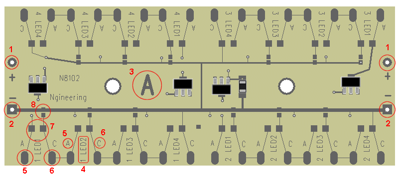
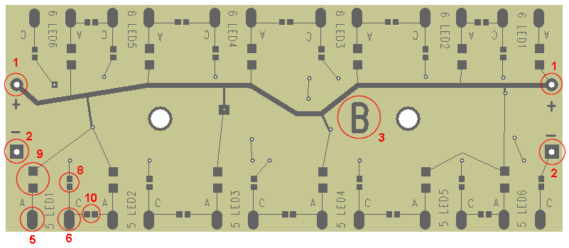
Figures 1 & 2 show front and back views of the N8102. Layout details are noted by a red circled area and corresponding number. The corresponding numbers are described below:
-
Solder points at both ends of the board for +DC wiring connection. This allows daisy-chaining of multiple boards (power bus wiring) for layouts & dioramas that have multiple area that will contain lighting. More information about connecting multiple boards can be found here.
-
Ground or ĖDC connections (same as #1)
-
Large letter A (front of board), or B (rear of board) for easy reference in documentation. A-side uses 20ma current sources (4 separate ones), which support 4 LED solder pad groupings for up to 4 LEDs in series each for a total of up to 16 LEDs (depending on supply voltage available). B-side is for LEDs using resistors and can be connected as series groups or individual (parallel) LEDs.

Figure 1
-
Shows how an individual LED hookup is marked. The first number is the group number 1-4 on A-side, 5 & 6 on B-side). The second part is the LED number of the group (for example LED2).
-
Notes the solder pad for wire connection to the anode (+) of the first LED of group 1.
-
Notes the cathode (-) wire hookup point.
-
Since LEDs on A-side use a 20ma current source, by default, they will shine at full (20ma) brightness. Should the user wish for some reason, to reduce the current going through a particular LED on side-A, a pair of solder pads is provided for soldering a resistor for brightness adjustment. Note: even though you may have up to 4 LEDs in a series group, the brightness for each individual LED can be adjusted differently, if desired. This provides total control.

Figure 2
- On to side-B of the board. In a typical LED connection to a power source, an LED requires a resistor for current protection. These solder pads are for installing a resistor and note that one of the pads is connected to the + DC circuit. Again, 5 notes the anode (+) LED solder pad. Also note the cathode solder bridge point 8. If for example, LED1 of group 5 were to be connected as an individual (not series group) LED, its cathode bridge would be soldered to complete the circuit. Now letís suppose that you wanted LED1 and LED2 of group 5 to be a series pair. In this case, you would not solder bridge LED1ís cathode. Instead you would solder bridge point 10 (which will connect LED1ís cathode to LED2ís anode) and then solder bridge LED2ís cathode. In this case, the resistor selected for LED1ís anode would be calculated for use with the series pair.
With this flexibility, side-B of the distribution board can be setup any way the user wants. For example, group 5 could be 6 individual resistored LEDs, 6 LEDs in series, 3 groups of series pairs, or 3 in series and 2 in series and 1 individualÖ or any combination needed.
© 2008 Ngineering


