


Best viewed using:
Internet Explorer
or
Mozilla Firefox


N8108-02 & -03 7-LED Arrow Bar for Police Vehicles
Description of Lighting Effects
The N8108-02 Simulator is designed to provide centralized connection for LEDs connected to pad pairs A through G, which simulate a 7-light traffic arrow as used by modern police vehicles. Arrow direction control is also available.
The N8108-03 Simulator is designed to provide centralized connection for LEDs connected to pad pairs A through G, which simulate a 7-light traffic arrow as used by1970's era police vehicles. Arrow direction control is also available.
DC power
input is connected to the
DC+
and
DC–
solder pads as
indicated in Fig.1 below.
This module
does not support filament
type
bulbs.
Utilizing the one of the
industry’s
most advanced
microcontrollers and
highly regulated voltage control
circuitry, this
total module consumes less than
140ma of
current during normal operation with all LEDs attached. The 8-component
switching buck regulator circuit maintains on-board power regulation within 2%
while input voltage can range from 7.5 to 20 volts DC.
All connected LEDs are supported by
on-board resistors for current protection (and brightness balancing).
Connecting the N8108-02 & -03
These module’s
tiny size will allow them to be placed
so they are easily hidden from view. They
only
have circuitry on
the board top side. The bottom of the board is electrically –DC and can
be used for mounting with the small square double-sided sticky foam pad that is
included in this package.
Included
with each module are
four 6” lengths of #32 insulated wire (red, black & two violet wires).
These can be used for power input wires & control wires.
If used, the red wire should be soldered to the +DC solder pad, the black
to the –DC pad. The violet wires can be used for grounding (–DC) pads
H
& J to initiate the arrow effect.
Important note:
A
low-wattage
iron with a pointed tip should be used for connection of wires. Too much
heat or solder can easily damage the wires
or module and void the warranty.
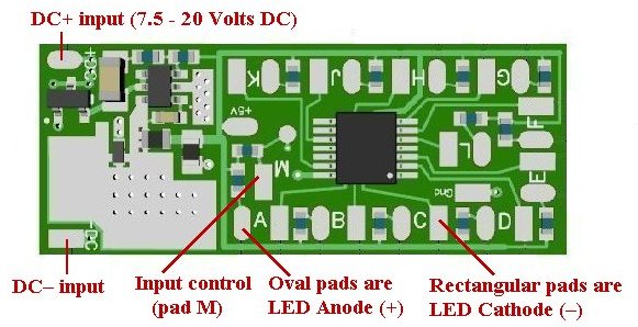
Figure 1
Also, all connecting wires should be pre-tinned before soldering them to the module. This will make connection quick and easy and ensure excessive heat is not applied to the solder points.
Connecting LEDs
When
connecting the
wired
LEDs, proper polarity must be observed. LEDs
are “polarity sensitive” and will not function if connected backwards. The
N8108 is designed to provide for easy visual determination of proper LED
polarity. As shown in Figure 1, There are solder pad pairs on the board
designated as A, B, C, D, E, F, G. The
oval shaped pads
are for
+
(anode) LED
connections, and the
rectangular pads are for the – (cathode) LED connections.
Rectangular
pads H &
J are for input (arrow
direction) control. Grounding pad H will cause arrow sequencing
from left to right, grounding
J will sequence from right to left. DO NOT ever
ground both
H &
J at the same time, or circuit
damage will occur.
N8108-02 Arrow-bar & program
configuration:
1
LED on pad pair ‘A’ (blue LED) & LED on pad pair ‘G’ (red LED)
alternately flash a double-pulse strobe every 0.3 seconds.
2. At the
same time, LEDs on pad pairs ‘B’ thru ‘F’ turn on sequentially and stay on at
0.6 second intervals.
3. After ‘B’
thru ‘F’ are all on they flash off & on two times.
4. The
sequence start over at 1.
Pads ‘H’ and
‘J’ control arrow sequence directions as noted above by grounding (–DC) either
of these pads. This makes it easy for RC applications.
A
double-throw single pole switch with the center pole (wiper) connected to ground
can also be used for stationary applications.
N8108-03 Arrow-bar & program
configuration:
1. LEDs on
pad pairs ‘A’ thru ‘G’ turn on sequentially at 0.8 second intervals and stay on
.
3. After ‘A’
thru ‘G’ are all on they turn off, then flash on once.
4. The
sequence start over at 1.
Pads ‘H’ and
‘J’ control arrow sequence directions as noted above by grounding (–DC) either
of these pads. This makes it easy for RC applications.
A
double-throw single pole switch with the center pole (wiper) connected to ground
can also be used for stationary applications.
Figure 2
below shows LED wiring connections to pad pairs for the 7-LED Arrow Bar Police
Vehicle Simulator board.
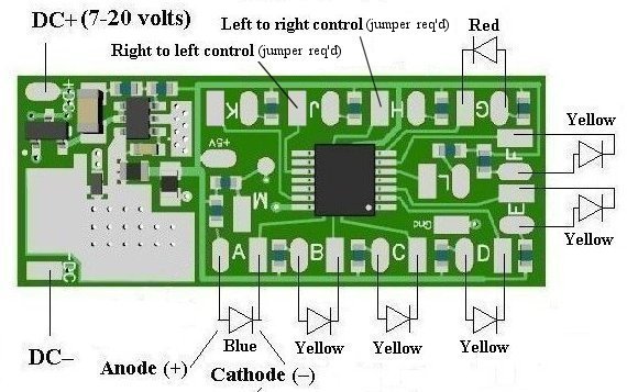
Figure 2
NOTE:
Input solder pads for arrow direction control
(pad pairs
H & J) require a control wire to
be solder jumpered across both the
oval and rectangular pads as shown in Figure 3 below.

Figure 3
WARNING!:
When
soldering the jumper wire on pad pair
H ensure
the stripped jumper wire is twisted and pre-tinned, AND,
MAKE SURE
the jumper and/or solder
DOES NOT
contact the circuit trace running between the pads.
This
completes configuration and setup instructions for the Arrow bar lighting
effects Simulator board.
We hope the
added realism brings enjoyment to your hobby project that it deserves.
If you need
assistance please contact: [email protected]
© 2024 Ngineering