


Best viewed using:
Internet Explorer
or
Mozilla Firefox


Connecting the NL8014B (bi-directional) Constant Voltage Circuit
Connecting the NL8104B is quite simple. This circuit is designed for bidirectional track polarity so it will function for both DC (analog) and DCC operations and function in both forward and reverse motion operations. It is configured for up to 3 LEDs of the 3.3-volt (white variety - white, warm-white, incandescent, yellow-white, sunny white, etc.)type.
Figures 1 and 2 below highlight the components and connection points of the circuit..
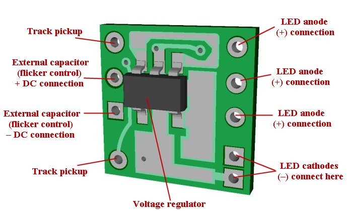
Figure 1
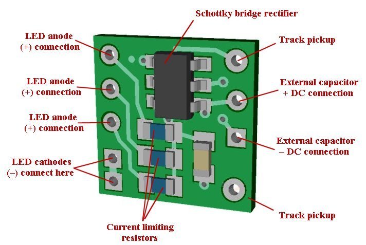
Figure 2
LED connections:
Note: LEDs are polarity sensitive devices and must be wired with their anodes (+), and cathodes (–) connected to the proper solder points as shown.
Caution! Carefully inspect all anode and cathode solder joints for solder bridges or shorted wires. Permanent damage to the circuit will occur if these outputs are shorted when power is applied.
Flicker control:
Another new feature we've added to our N8104B modules is solder-points for direct wiring of external capacitors for flicker control. When connecting external capacitance for this purpose, if multiple capacitors are used, they must be wired in parallel (all + connections together, and all – connections together). They must have a voltage rating of 16-volts or greater. The + (plus) connections are to be wired to the solder point noted as "External capacitor + connection", and the – (minus) connections are wired to the "External capacitor – connection". A total of 500-800uf of capacitance should be sufficient for flicker control of the 3 LEDs.
Be sure to use a low-wattage soldering iron when connecting wires to the module. Our N40M2 12-watt Iron with either the N408I (iron clad) Needle Tip, or the N408X (bare copper) Needle Tip would be an excellent choice for this operation (or any DCC decoder work).
This completes electrical hookup of the NL8104B Constant Voltage Circuit.
© 2014 Ngineering