


Best viewed using:
Internet Explorer
or
Mozilla Firefox


Constructing a 4-LED Beacon for the N8042C Simulator
Constructing the 4-LED beacon:
Building the 4-LED beacon assembly is very straightforward. A sub-assembly
of 2 LEDs are soldered together and a wire is attached. Two of these 2-LED
sub-assemblies are required. They are joined by soldering a third wire
(common) attached to the top of these 2 sub-assemblies along with a solder
bridge connecting the top ends of the 4 LEDs. The 3 attached wires connect
to the module solder points 3, 4 & 5.
For N and Z scale, we recommend our Nano LEDs and N5038 #38 magnet wire.
For HO and O scale, we recommend our Micro LEDs and our N5038 #38 magnet wire
The following graphics show construction of a RED LED beacon assembly using our Nano LEDs (note the ‘C’ shaped solder pad is the ANODE or + connection). For all other LED colors (including white) the ‘C’ shaped solder pad is the CATHODE (-) and the LEDs need to be orientated in reverse as shown here in Figure 1.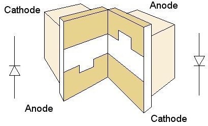
Figure 1
Figure 1 above shows 2 LEDs located against each other with one at right angles to the other. Styrene shim stock or other material can be used to help position the LEDs at right angles with the sides touching as shown. Whatever shimming material is used, it is very important that the LEDs be held in position so that during soldering they do not move.Figure 2 below shows that the two LEDs are joined by a small solder connection (left LED cathode, right LED anode). Our N40m2 12-watt soldering iron with the N408I needle tip is ideal for this soldering operation. Using low-temperature solder such as our N4200 is also very helpful to minimize temperature stress on the LEDs.
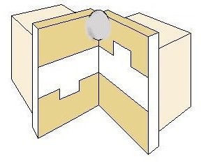
Figure 2
Figure 3 and 4 below shows the addition of the connection of a pre-tinned wire attached to the LED pair at the left LED anode, right LED cathode position. This completes the first LED sub-assembly pair. Repeat the steps in Figures 5 through 7 to create a second LED sub-assembly pair.
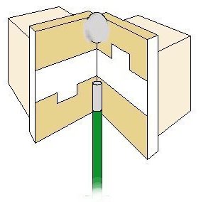
Figure 3
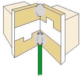
Figure 4
When soldering the wire, make sure it lays flat against the solder pad on the LED as shown and the solder joint is smooth and low (not lumpy). Observe the recommended LED soldering temperature precautions. A small amount of liquid flux will assist soldering.
Figure 5 below shows two of the LED-pair sub-assemblies oriented so that they form a 4-LED square with the unsoldered sides close to other but not touching. To help facilitate this a flat piece of styrene or other material with a small (#79) hole drilled through it to feed the 3 wires down, will help. This flat piece of material will provide a temporary “base” for the LEDs to sit against. Small pieces of styrene of other material should be used to help position the 2 sub-assemblies so the are oriented as shown and do not move during the next soldering operation. Again, it is very important that the unsoldered bottom edges of the adjacent LED pairs do not touch each other. You will also notice in Figure 5, a pretinned wire sticking up in the middle of the 4 LEDs. The pre-tinned end of this wire should be cut short so that the tinned portion is no longer than the height of on of the LED’s solder pads.
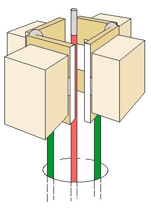
Figure 5
In Figure 6 below, this center wire (common) is bent over it hangs between the top solder pads of the 2 adjacent sub-assemblies.
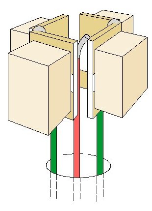
Figure 6
Figure 7 below, shows this wire is soldered joining itself and the top 2 adjacent solder pads of the 2 adjacent sub-assemblies. An additional solder joint connects the oposite 2 adjacent top solder pads as shown. Now this center (common) wire has been electrical joined with all 4 top solder pads on all 4 LEDs. This completes the connection for the 4-LED beacon assembly and it can carefully removed from the holding fixture and tested. Using an LED tester (such as our N8021), connect the common and one of the other wires to the tester. One of the LEDs should light. Switch the wires on the tester and the other LED of the pair should light. Repeat this procedure with the common wire and the other wire and the other 2 LEDs should each light. Once testing is complete the beacon can be mounted in your model and wired to the N8042C Simulator module. The common wire is connected in series with a resistor (included in the Simulator package with a spare) to solder point 4. The other wires are connected to points 3 & 5.
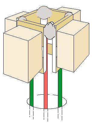
Figure 7
This completes construction and connection of the 4-LED rotating beacon assenbly.
© 2008 Ngineering